# Flashing and debugging
The firmware of embedded devices is usually stored in the flash memory of the microcontroller. In order to upgrade it, special tools and processes may be needed. This chapter will give an overview of the most important aspects you need to know about firmware upgrades.
There are basically two ways to upgrade the firmware.
Using a programmer and a dedicated hardware interface (JTAG/SWD) on the board to communicate with the microcontroller.
Via a bootloader using communication interfaces that are used for other purposes during normal operation of the device.
Both methods will be explained in more detail below.
# Programmer
In most cases the chip is programmed while it is already soldered onto the board, called In-System-Programming (ISP). For very large production quantities, the initial version of the firmware (or only the bootloader) can be programmed already to the microcontroller by its manufacturer before soldering it to the board.
For ISP, the microcrontroller has to be set into programming mode (e.g. via the reset pin) and special connectors or pin headers are needed to access the programming interface of the microcontroller.
Microcontrollers based on ARM Cortex-M like the STM32 series feature the Serial Wire Debug (SWD) interface for programming and debugging. This is the most common architecture for 32-bit Microcontrollers and is also used in the Libre Solar charge controllers and other devices, so the following sections focus on programming via SWD.
# ST-Link
For development with STM32 microcontrollers, usually the ST-Link in-circuit debugger is used for programming. All ST Nucleo development boards include an integrated ST-Link/V2 debug adapter. The boards are very cheap and allow not only firmware upgrade but also debugging via the SWD interface (see also section Debugging).
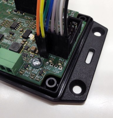
The Libre Solar boards usually contain a 5-pin or 6-pin header with the same pin-out as the SWD connector on the ST-Link/V2 of the Nucleo boards. In addition to that, you can use the serial interface built-in to the Nucleo board to transfer debug information via an additional 2-pin connector.
WARNING
Before you can flash the software, the device needs to be powered, either via USB or the battery. The VCC from SWD does not provide power, it just detects the supply voltage of the target.
The same pins of the SWD connector on both boards should be connected with jumper wires. Pin 1 is usually marked with a small dot next to the connector. The following table gives an overview of the connector pinout:
| Pin function | Nucleo board | Libre Solar board |
|---|---|---|
| VCC | SWD pin 1 | SWD pin 1 |
| SWCLK | SWD pin 2 | SWD pin 2 |
| GND | SWD pin 3 | SWD pin 3 |
| SWDIO | SWD pin 4 | SWD pin 4 |
| NRST | SWD pin 5 | SWD pin 5 |
| SWO (optional) | SWD pin 6 | SWD pin 6 |
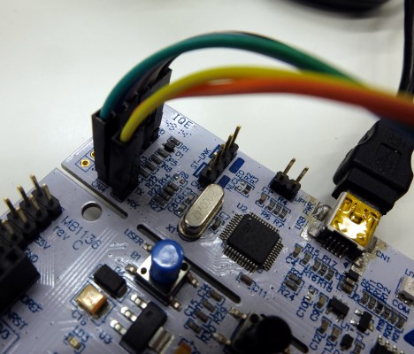
Important note: The jumpers at the CN2 connector of the nucleo board have to be removed (see also picture below) in order to flash the external device connected via the SWD connector. Otherwise, the software will be flashed to the integrated MCU.
The USART serial interface connection is optional, but very useful during development for sending messages between the device and the computer. The wires have to be connected according the following table:
| Pin function | Nucleo board | Libre Solar board |
|---|---|---|
| UART serial | CN3 pin 1 (RX) | TX pin |
| UART serial | CN3 pin 2 (TX) | RX pin |
Please note that TX and RX are crossed between the boards. The receive pin (RX) of one board connects to the transmit pin (TX) of the other board.
The following figures show the location of the connector on the Libre Solar MPPT 2420 LC and the Nucleo board.
Once the connection is set up properly, you can press the flash button on the computer (e.g. using the PlatformIO plugin together with VS Code).
# Segger J-Link
For more advanced debugging purposes, the commercial Segger J-Link (opens new window) is a very popular tool. The main advantage is probably the software provided by Segger that can only be used together with the J-Link.
# Black Magic Probe
Another very popular programmer and debug probe for SWD is the Black Magic Probe (opens new window). It is Open Source and supports multiple different MCUs.
# Bootloader
A bootloader is a small program on the microcontroller that is started before the normal application. If the bootloader detects that the firmware should be upgraded (there are several ways to indicate this as discussed below) it provides the interface between the external world and also writes the new firmware to the flash. During normal startup, the bootloader just starts the original application.
A well-known example for a device using a bootloader is the Arduino. Together with the USB to serial converter on the board it allows to upgrade the Arduino firmware via the same serial interface that is also used for communication with the device (Serial.println() functions etc.).
# Types
Bootloaders can be categorized by how they transfer the data and how the firmware upgrade is initiated.
# Transfer of data
If it is acceptable that the application is stopped during firmware upgrade, the bootloader itself can be responsible for the data transfer from the host or server to the device. The device resets, starts into the bootloader, performs the firmware upgrade and afterwards starts into the updated application.
However, if the firmware should be upgraded in the background so that the user doesn't even notice it, the firmware image can be downloaded by the application software during operation. In this case, the bootloader can be very simple and is only needed for switching between the old and the new image (or overwriting the old firmware) after the download has finished.
It can also make sense to download the firmware image from a server by the application itself if a higher-level communication interface is used (e.g. internet connection instead of just a serial port) that is already present in the application. This approach saves considerable amount of flash memory if the bootloader does not need to implement the entire networking stack aswell.
# Initiation
A firmware upgrade can be triggered manually or run automatically in the background.
For an automatic upgrade in the background, the application firmware needs to check a server for firmware updates and pulls new updates automatically if available.
More simple firmware upgrade methods intended to be used with local access to the device usually trigger the firmware upgrade manually. This can be done by setting a dedicated pin to a defined state during reset (e.g. the BOOOT0 pin of STM32 MCUs) or by sending a command to the device to enter the bootloader.
Libre Solar devices with a reset button enter the internal STM32 bootloader (see below) by pressing the reset button for 3 seconds. If the devices don't have a reset button, the bootloader can be entered by sending the ThingSet command !exec/bootloader-stm via the serial interface.
# Examples
The following table gives an overview of some popular bootloaders:
| Name | Data transfer | Initiation |
|---|---|---|
| MCUboot (opens new window) | application | automatic |
| OpenBLT (opens new window) | bootloader | manual |
| Arduino Optiboot (opens new window) | bootloader | manual |
| STM32 internal (opens new window) | bootloader | manual |
# DFU via USB
The STM32 microcontrollers feature an integrated bootloader that can be used via different interfaces like UART, USB and CAN (depending on the MCU). As this bootloader provides a very cheap and reliable way of firmware upgrade it is supported by most of the Libre Solar devices. The firmware upgrade via the USB interface is explained below.
The firmware upgrade via USB interface does not need any additional hardware except for a USB cable. For the Libre Solar devices, a Micro USB connector is used.
Device Firmware Upgrade (DFU) is an official USB device class specification. It is natively supported by Linux and Mac. For Windows you need to install some drivers. The details about use of the bootloader are explained in this excellent article by Adafruit (opens new window).
# Debugging
In order to find bugs in the firmware, people often use a serial interface and print debug messages to it. However, this approach consumes lots of time and does not allow systematic tracing of issues as soon as the firmware reaches a higher degree of complexity.
The SWD interface in above mentioned programmers can be used to communicate with the device while the firmware is running and obtain live data from the device's memory.
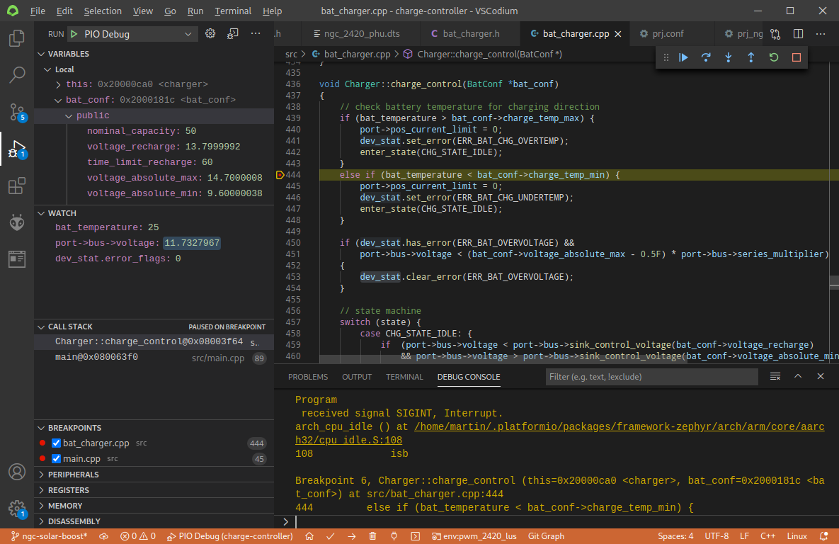
With PlatformIO and Visual Studio Code no complicated tools are needed for full-featured debugging interface and you get a graphical debugging interface as shown in Figure 3.
The biggest advantages of using a debugger instead of serial prints:
- The firmware execution can be stopped at defined break points in order to analyze the state of the memory at this point.
- Variables can be watched live while they are changing and you don't need to re-flash if you forgot one variable in the print statement.
- Variables (or data in memory in general) can even be changed via the debug interface.
- If the program crashes at an unknown location you can step through the code until you reach the location where it crashes.
For further information how to set up the debugging environment refer to the PlatformIO Debugging documentation (opens new window).