# Grid Architecture
A DC grid allows to interconnect multiple energy sources and sinks.
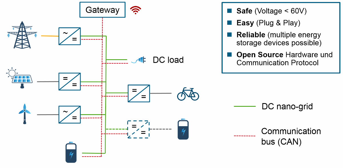
Compared to conventional AC grids, where the energy flow is mostly uni-directional from the energy source to the consumer, the proposed DC grid as shown in Fig. 1 can operate in both directions. A battery for example can be a current source or a current sink.
The main system level functions of the grid are:
- Current routing (wired connection between devices including switches and fuses)
- Voltage control (e.g. to set correct battery charging voltages)
- Energy management (management of the state of charge of the batteries)
The overall system is divided into abstract sub-components, as described below. These components don't necessarily need to be separate physical devices, but can be combined in a single device.
# Current routing
The components of the DC grid are electrically connected to each other via cables. The current flow takes the path of lowest impedance between the devices and can be controlled by current interrupt devices (e.g. circuit breakers) for safety reasons and to optimize energy management.
# DC bus
Connection of two or more electrical circuits such that the electric potential at each connection point can be considered equal. This can be achieved either by connecting each participant very close to each other or by using large copper cross-section such that voltage drop introduced by current flow is negligible.
The cross section of the conductor must be large enough to handle the sum of the maximum current of all connected sources.
# Power line
Bipolar connection (cable) between exactly two grid ports. Splices are not allowed.
A power line might cover long distances, resulting in a voltage drop caused by the resistance of the cable. The voltage drop has to be considered to allow stable system control.
# DC grid port
Connection between a DC bus and a power line, featuring
- a fuse, circuit breaker or electronic switch to allow disconnection of the port and
- measurement of port current and bus voltage (optional).
# Voltage control
The voltage in a DC system depends on the open circuit voltage of the connected voltage sources and the drop caused by the actual current flow via the included resistances (e.g. wire resistance, internal resistance of a battery).
The voltage of the bus can be either dominated by a connected battery, or can be independently controlled if batteries are connected to the bus via a DC/DC converter.
# Battery-dominated voltage
If a battery is hard-wired to the DC bus, the open circuit voltage (OCV) of the battery defines the bus voltage without load. Under load, the voltage changes depending on the battery internal resistance and wire resistances.
For charging a battery, the voltage limits of the battery (charge profile) need to be communicated to all energy sources.
If multiple batteries are connected to the bus, all batteries need to be of the same type, otherwise valid charge profile control is very difficult.
# Voltage converters
A DC/DC converter allows to connect DC buses of different voltage levels, e.g. a battery or solar panel to the DC grid.
Using a voltage converter between all energy sources and the DC bus allows an independent control of the DC grid voltage.
In this case, the grid voltage is a measure for the system state and can be used for basic communication called DC bus signalling. A high voltage level, for example, means lots of available excess renewable energy in the system.
Load prioritization via different disconnect set-points is possible.
The chapter Droop Control further explains how power flows can be controlled based on the grid voltage measurement.
# Topologies
This overview of different grid topologies assumes a DC grid with droop control where every producer and consumer is decoupled from the grid via a voltage converter.
# Bus/star topology
The following image gives an example of a simple DC grid layout.

It consists of a centralized DC bus with large cross-section, large enough to carry the sum of the source currents of all connected devices.
Each connection from the bus to a power line needs a protected port to limit the amount of current.
# Meshed grid topology
If the grid contains a loop which allows redundant current paths, it is called a mesh.

The meshed topology requires additional current routers which make sure that none of the power lines gets overloaded.
The individual grid participants are daisy-chained in above picture. However, it is possible to connect any number of power lines to each DC bus as long as each port ensures that no individual power line is overloaded.