# Manual Check
Before the board is flashed with the firmware, some basic checks should be performed to see if the soldering process went well.
# Solder bridges
The board should be carefully checked for solder bridges between any pins. Especially microcontrollers with small pin pitch are susceptible to have some unwanted connections between pins.
Ideally a magnifying glass or a microscope is used to check the board.
If solder bridges are identified, they can be removed with solder wick (also called desoldering wire) as shown in Fig. 1.
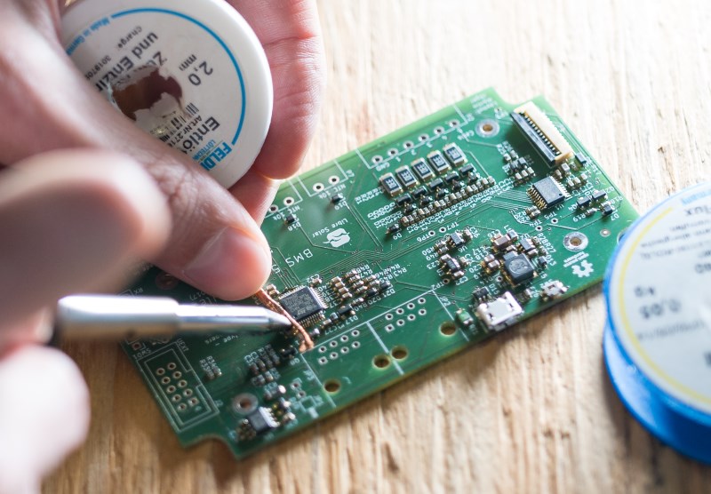
Ideally use a soldering tip with high mass and high temperature setting (around 400 °C) to heat up the solder quickly through the desoldering wick. You should not touch with the soldering iron for too long, so that not too much heat is transferred into the chip.
Lead-free solder needs higher temperature settings compared to old solder with lead.
# Supply voltage
After all solder bridges have been removed and you checked that all parts in the PCB are present, you can start to power the PCB, ideally through a current-limited laboratory power supply. The current limit should be set to a very low value to prevent damage in case of short circuits. Usually, 100mA should be enough.
If the PCB has a USB connector, it is most probably the easiest way to power the board. If existing, a power LED might directly indicate that the board is working. Libre Solar boards usually only contain LEDs which can be switched on or off by the microcontroller in order to reduce the standby power consumption. Such LEDs work only after flashing the firmware.
Without an LED as indicator, you need the multimeter to check if the power supply is working. It can be measured at the capacitors close to the microcontroller which should be at 3.3V. An example is shown in the following figure:
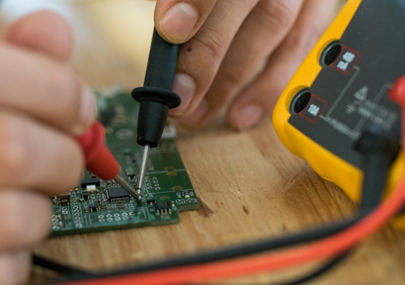
For more detailed analysis, the schematic and board files of the specific device has to be used to find possible additional points to test.
If you don't see the correct voltage at the capacitors, something must be wrong in the PCB, possibly a short circuit.
# Short circuits
Unfortunately, a short circuit cannot be detected easily with a multimeter. You might touch the PCB to detect if some parts get hot and look for the short circuit close to the hot parts.
If available, you can inspect the PCB using a thermal camera to detect hot spots with short circuits, as shown in Fig. 3.
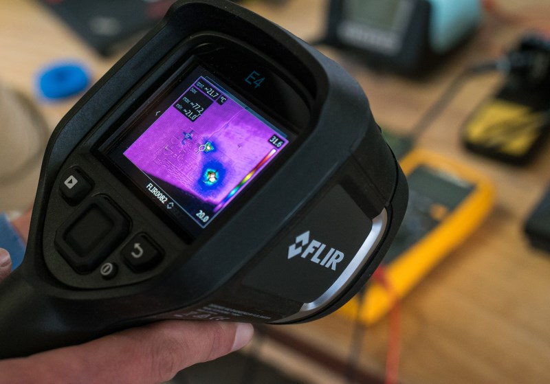
Areas with high current flow and resulting heat dissipation will get hot and show up as red spots in the thermal camera image. However, the hot location may not indicate the failure itself. If for example one of the capacitors in the 3.3V power supply is shorted, most probably the power supply will get hot and not the capacitor.